Laser Engraving Photo vs Vector: When to Raster, When to Cut
Your laser has two modes: raster sweeps that burn grayscale photos, and vector paths it cuts or scores. Here is how to tell which one a job needs and how to prepare each file.
Founder of VectoSolve
Self-taught developer, founder and sole developer of VectoSolve since 2024. He builds the conversion engine and the cutting, embroidery and 3D printing exports.
How this article was made: drafted with AI assistance, then edited and fact-checked before publication. About the author
Try it on your own file, in Laser mode
Free preview, no signup. Drop an image and see the vector before deciding anything.
When this guide says "vectorize", it means converting the raster to real paths — the image to DXF converter does that step for cutting workflows.
Two modes, one machine
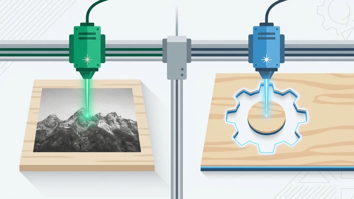
Every hobby and small-shop laser — CO2, diode, or fiber — executes jobs in one of two fundamentally different ways, and the file you send largely determines which one you get.
Raster engraving works like an inkjet printer. The head sweeps back and forth across the material in closely spaced parallel lines, pulsing the laser on and off (or modulating its power) as it passes over dark pixels. The input is an image: a grid of pixels. The output is a burned picture. Tone comes from dot density or power, and the whole area gets covered whether it needs to or not, which is why raster jobs are slow.
Vector cutting and scoring works like a plotter. The head follows a path — a mathematical curve with coordinates — from start to finish. The input is geometry, not pixels. And here is the part beginners miss: whether a path becomes a through-cut or a light surface line (a score) is not stored in the file at all. It is decided by power and speed at the machine. The same rectangle cuts through 3 mm plywood at high power and low speed, and merely draws a crisp line on the surface at low power and high speed.
Control software exposes this split directly. LightBurn's documentation defines its two core layer modes in exactly these terms: "Line Mode tells your laser to trace a path around the contours of vector graphics," while "Fill Mode tells your laser to etch parallel lines within the boundaries of vector graphics" — the spacing between those fill lines is set by the Line Interval, and Speed and Power control the darkness or depth of the etch (LightBurn Documentation — Layer Modes). Note what Fill mode implies: vector shapes can be engraved too, by scanning inside their boundaries. The raster/vector split describes how the head moves, not merely which jobs count as engraving. xTool's support center draws the same distinction for its machines: in Score mode, "only the outline of it will be processed"; in Engrave, "the closed area within the outline will be engraved"; and in Cut, "the graphic will be cut out through its outline" (xTool Support Center).
| Raster engraving | Vector cutting / scoring | |
|---|---|---|
| Head movement | Sweeps line by line, like a printer | Traces each path directly |
| Input | Pixels (JPG, PNG, BMP) | Paths (SVG, DXF, AI, PDF) |
| Grayscale | Yes — via dithering or power modulation | No — a path either fires or it doesn't |
| Cut vs. mark decided by | Not applicable (surface only) | Power and speed settings |
| Best for | Photographs, shading, texture | Outlines, text, parts, stencils |
| Job time | Slow — covers the full area | Fast — travels only the lines |
Everything else in file preparation follows from this split.
The classic failure: a JPG where a cut file should be
The most common beginner mistake looks like this: someone has a logo as a JPG, drops it into their laser software, and hits start. The software has no paths to follow, so it does the only thing it can — it raster-engraves the image. What was supposed to be a set of clean cut lines comes out as a slow, blurry burn. The anti-aliased pixels along every edge become a fuzzy gray fringe, JPEG compression artifacts show up as smudges in flat areas, and there is no cut at all, because there was never any geometry to cut.
Manufacturers make this constraint explicit. Glowforge's design-upload documentation states that files must be "SVG or PDF (for cutting and engraving), or JPG or PNG (for engraving only)," with DXF also accepted for Premium members (Glowforge Help Center). A bitmap cannot drive a cut or a score on that machine no matter what you do to the settings, because the file carries no geometry for the head to follow.
The reverse mistake exists too, and it is worse in a different way: auto-tracing a photograph into vectors. A tracer has to commit every pixel to a hard-edged shape, so a continuous-tone photo collapses into a handful of posterized blobs. All the tonal information that makes a photo readable is gone before the laser ever fires.
The rule that resolves both: match the mode to the content, not to whatever file you happen to have.
Vectorize it: logos, text, shapes, parts
If the artwork is made of distinct shapes — a logo, lettering, an icon, a stencil, a part that must physically fit something — the laser needs real vector geometry. That means converting the JPG or PNG into paths, not just renaming it or embedding it in an SVG wrapper (an SVG containing a bitmap is still a bitmap to your laser).
A purpose-built converter like our laser cut file converter traces the image into clean paths and exports SVG or DXF sized for cutting. The watermarked preview is free with no signup, so you can test it on your actual file before deciding anything.
Two honest caveats about tracing, because they will bite you if nobody mentions them:
- Tracers produce outlines, not centerlines. A thin stroke in the original becomes two parallel paths — one down each side. For cutting that is usually what you want (the stroke becomes a physical sliver or a slot). For scoring single-line text, it means the laser draws both edges of every letter stroke. If you want true single-line lettering, use a single-stroke font in your laser software instead of tracing rendered text.
- Tracing quality is bounded by input quality. A 200-pixel-wide logo screenshot traces into lumpy curves no matter which tool does it. Feed the tracer the largest, cleanest source you have.
A Full Year of Conversions for $49
Starter Annual: 25 conversions every month, $49 for the whole year. That is about $4.08 a month · Cancel anytime
Get the Annual DealKeep it raster: true photographs
A photograph of a face, a pet, or a landscape should stay a bitmap. The preparation problem is different: most lasers are effectively binary at any given point — the beam fires or it does not — so continuous tone has to be faked with dithering, the same trick newspapers used for decades. Error-diffusion algorithms like Floyd–Steinberg, Jarvis, or Stucki convert grayscale into a pattern of discrete dots whose density reads as tone from arm's length. This is standard enough that LightBurn ships ten image processing modes — Threshold, Ordered, Atkinson, Dither, Stucki, Jarvis, Newsprint, Halftone, Sketch, and Grayscale — and its documentation singles out the error-diffusion options for photographs, calling Jarvis "usually the best choice for smooth shaded or photo images" (LightBurn Documentation — Image Mode). Many diode engravers also offer a grayscale mode that varies power per pixel instead; it works well on wood but is harder to dial in.
The practical prep sequence:
- Resize the photo to its final physical size first, at a resolution that matches your machine's line interval. The math is simple: at a 0.1 mm interval, the laser draws 25.4 ÷ 0.1 = 254 lines per inch — LightBurn's Image Mode documentation states the same relationship as "DPI is 25.4 / Line Interval" — so preparing the image at roughly 254 DPI at final size gives you one pixel per laser line. More resolution than that is discarded; much less gets visibly soft.
- Push contrast harder than looks right on screen. Wood and slate compress the tonal range dramatically. A photo that looks slightly overcooked on your monitor usually engraves correctly.
- Dither as the last step, after all resizing — scaling a dithered image destroys the dot pattern.
- Test on the actual material. The same file behaves completely differently on plywood, slate, and anodized aluminum. A material test card — a grid of power/speed combinations you engrave once per material — replaces guesswork with a reference tile you keep next to the machine. It's free to generate.
Two calibrations from the manufacturers are worth knowing here. Resolution has a hardware ceiling — Glowforge specs its machines at up to 1355 DPI engraving with positioning precision of 0.001 in (0.025 mm), on a 40–45 W CO2 tube depending on model (Glowforge Tech Specs) — but your useful resolution is set by the line interval you choose, not the spec sheet. And more lines per inch is not automatically better: according to Glowforge's manual-mode documentation, at low LPI the laser spots barely overlap, which shows up as stripes in the engrave and jagged edges on curved shapes, while at high LPI the spots overlap — smoothing the appearance but also engraving deeper, because the beam passes over the same spot more than once and removes material each time. Depth, speed, and smoothness move together; pick the interval for the material and the look, then prepare the file to match it.
Vectorization plays no role here. That is not a limitation of any particular tool; it is what vectors are.
Preparing a vector file that actually cuts
Once you have geometry, three things separate a file that cuts cleanly from one that ruins a sheet.
Closed paths. A cut outline must end where it began. An open contour — a gap of even a fraction of a millimetre, often invisible at screen zoom — means the piece stays attached, fills behave unpredictably, and offset operations fail. Gaps come from sloppy tracing, from booleans that almost merged, and from exports that split curves at node boundaries.
Real-world size in millimetres. SVG has a unit trap: one inch is 96 user units, and a file authored in bare pixels carries no physical size at all. A logo drawn 300 units wide might import as 300 ÷ 96 = 3.125 in ≈ 79.4 mm in one program and as 300 mm in another. For decorative work that is an annoyance; for a part that must mate with another part, it is scrap. Always confirm the document declares physical units and that a known dimension measures correctly before cutting.
Kerf, when parts must fit. The beam has width, and the cut removes material — the kerf — centered on the path. Published trade figures from CutLaserCut, a UK laser-cutting service, put kerf between 0.08 mm and 1 mm depending on material and conditions, with typical values around 0.18 mm on 1–3 mm acrylic, 0.20 mm on 3 mm birch plywood, and 0.16 mm on 3 mm MDF, rising to roughly 0.30 mm on 10–15 mm acrylic (CutLaserCut). So if your total kerf is 0.2 mm, each edge of a part loses half of it: a square drawn at 50.0 mm measures about 49.8 mm after cutting, and the hole it came out of measures about 50.2 mm. For finger joints, boxes, and press-fits, offset outer contours outward and holes inward by half the kerf. No file converter can know your kerf — it depends on your lens, focus, material, and thickness — so measure it once per material with a simple test cut and record it.
For downstream CAD/CAM work, convert the SVG to DXF — the export can split the output onto named CAM layers (CUT, ENGRAVE, and SCORE presets), so your CAM software can organize the geometry on import and you assign settings per layer. And if the design needs to bend, don't hand-draw the hundreds of short parallel cuts a flexure requires; a living hinge generator produces the pattern parametrically from panel size, cut spacing, cut length, and link gap. Test a strip on scrap first — how tight a bend the hinge survives depends on your material.
Verify before you burn
Material is the real cost of a bad file. Before committing a sheet, run the file through the cut file checker — it scores the file 0–100 and flags open contours, missing physical units, and other geometry problems, free, before the laser ever moves. Our converter's Machine-Verified Export applies the same idea at export time: it checks that contours are closed and that the document carries real millimetre dimensions, so the two failure modes above are caught before download rather than discovered on the machine.
To be clear about the boundary: verification covers the file. It cannot know your machine's kerf, your material, or whether 60% power at 20 mm/s cuts or merely scorches — that is what the test card and a scrap corner are for.
Free SVG Tools for Crafters
Design Checker · Color Separator · Mat Preview · Offset Generator · Text to SVG
Check Your SVG FreeFAQ
Can I vectorize a photograph so my laser can cut it?
Not usefully. Tracing forces every pixel into a hard-edged shape, so a continuous-tone photo collapses into posterized blobs. Photos belong in raster mode with dithering. Vectorize the things that are genuinely made of shapes: logos, lettering, silhouettes, parts.
What resolution does a photo need for engraving?
Match your machine's line interval at final size. At a 0.1 mm interval the laser resolves 254 lines per inch, so about 254 DPI at the engraved dimensions is the useful ceiling. Extra pixels beyond that are simply thrown away.
Why does my vector job only mark the surface instead of cutting through?
The file is fine — cut versus score is a machine setting. Lower the speed or raise the power (or add passes), check focus height, and dial in the combination on a material test card rather than on your workpiece.
Should I export SVG or DXF?
Most laser control software accepts both. SVG is convenient for direct-to-laser work; DXF is the standard when the file passes through CAD or CAM software, and our SVG to DXF export offers named CAM layer presets (CUT, ENGRAVE, SCORE) so the toolchain can assign settings per layer on import.
Sources
- LightBurn Documentation — Layer Modes — official definitions of Line mode (contour trace) and Fill mode (parallel scan lines spaced by the Line Interval, darkness/depth set by Speed and Power).
- LightBurn Documentation — Image Mode (Cut Settings) — the "DPI is 25.4 / Line Interval" relationship and the ten image processing modes, with Jarvis/Stucki/Dither recommended for photographs.
- xTool Support Center — What is the Difference between Engrave, Score, and Cut? — official definitions of the Score (outline only), Engrave (filled interior), and Cut (through-cut along the outline) processing modes.
- Glowforge Help Center — Upload Your Own Design File — accepted formats: SVG/PDF for cutting and engraving, JPG/PNG for engraving only, DXF for Premium members.
- Glowforge Tech Specs — engraving up to 1355 DPI, positioning precision to 0.001" (0.025 mm), 40–45 W CO2 tube ratings.
- Glowforge Help Center — Working With Manual Mode — how lines per inch affects banding, edge smoothness on curves, and engrave depth.
- CutLaserCut — Understanding Laser Kerf When Cutting — measured kerf range of 0.08–1 mm with per-material figures for acrylic, birch plywood, and MDF.
VectoSolve — AI-powered SVG platform: image-to-vector conversion, AI animation, brand identity generation, and more. https://vectosolve.com