
How to Convert PNG to DXF for CNC Machines — Step-by-Step Guide
Need to convert a PNG image to DXF for your CNC router or laser cutter? This guide walks you through the process from image preparation to machine-ready files.
Try it on your own file: free preview, no signup.
See plansHere for the file rather than the guide? The PNG to DXF converter traces your PNG and writes the DXF in one go: closed R12 polylines, one layer per colour, units declared in the file.
Founder and developer of VectoSolve
Self-taught developer who founded VectoSolve in 2024. He builds the conversion engine and the cutting, embroidery and 3D printing exports, working with the VectoSolve team of graphic designers.
How this article was made: drafted with AI assistance, then edited and fact-checked before publication. About the author
Key Takeaways
- CNC machines need vector paths (DXF), not pixels (PNG) — toolpath generation is impossible from raster images
- The reliable workflow is PNG → SVG (via AI tracing) → DXF export, not direct PNG-to-DXF
- DXF version matters: R12 is the universal safe bet for CAM software compatibility
- Always check for open paths and overlapping nodes before sending a file to the machine
- Feed rates and bit selection vary dramatically by material — get these wrong and you'll break bits or burn stock
If you've ever tried to load a PNG into your CAM software and watched it do absolutely nothing useful, you already know the problem. CNC routers, laser cutters, and plasma tables don't speak pixels. They speak toolpaths — precise mathematical instructions that tell the spindle or laser head exactly where to move, how fast, and how deep.
This guide walks through the full workflow for getting a PNG image into a machine-ready DXF file, with the real-world considerations that matter behind the controller.
Not sure which converter to trust? We checked which JPG/PNG to DXF converters actually vectorize and which just wrap pixels in a CAD container.
Why CNC Machines Need DXF, Not PNG
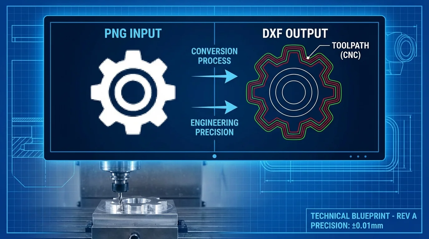
A PNG is a grid of colored dots. Your CNC controller needs something fundamentally different: vector geometry — lines, arcs, curves, and closed contours that define precise boundaries.
When your CAM software (Fusion 360, VCarve, Mastercam, LightBurn) generates a toolpath, it's doing math on those vectors. It calculates cutter compensation, lead-in moves, ramp angles, and step-over distances. None of that is possible from a pixel grid. You'd be asking the machine to "cut along the edge of this blurry JPEG," and it simply can't.
DXF (Drawing Exchange Format) is the industry standard for exchanging 2D vector geometry between CAD/CAM systems. Originally developed by Autodesk, it stores points, lines, polylines, arcs, circles, and splines — exactly the entities your CAM software needs to build toolpaths.

Step-by-Step: PNG to SVG to DXF Workflow
Here's the workflow that actually works in production. Forget "direct PNG to DXF" tools — they produce garbage. The reliable path goes through SVG as an intermediate format.
Step 1: Prepare Your Source Image
Garbage in, garbage out. Before any conversion:
- Use high-contrast images with well-defined edges (minimum 300 DPI for detailed work)
- Remove busy backgrounds — use VectoSolve's background remover to isolate your subject
- For logos and text, black-on-white source art traces dramatically better than colored originals
- Scan hand-drawn designs at 600 DPI for the cleanest vector output
Step 2: Convert PNG to SVG with AI Tracing
Upload your prepared PNG to VectoSolve's vectorizer. The AI-powered tracer analyzes your image and generates clean vector paths — far superior to threshold-based autotracing that produces jagged, over-noded outlines.
What makes AI tracing different: it understands intent. It recognizes that a slightly wobbly hand-drawn circle should become a smooth arc, not a polygon with 200 nodes. This matters enormously when those vectors become toolpaths.
Pro Tip: Before exporting your SVG to DXF, optimize the vector paths. Reduce node count where possible, merge overlapping shapes, and ensure all cutting contours are closed paths. Five minutes of cleanup in VectoSolve's SVG editor can save you thirty minutes of headaches in your CAM software. Simpler vectors = cleaner toolpaths = better cuts.
Step 3: Export SVG to DXF
Use VectoSolve's SVG to DXF converter or your PNG to DXF direct pipeline. The key decision here is which DXF version to export.
Step 4: Import DXF into CAM Software and Generate Toolpaths
Open your DXF in your CAM software and assign toolpath operations to each vector element:
- Fusion 360 — File > Insert > Insert DXF, then switch to Manufacturing workspace
- VCarve Pro — File > Import > Import Vectors, then use toolpath panel
- LightBurn — File > Import (native DXF support, auto-assigns layers)
- Easel (Inventables) — Import > DXF file, then set cut depths per element
- Mastercam — File > Converters > DXF, with full entity mapping
DXF Version Compatibility Guide
Not all DXF is created equal. Older CAM software chokes on modern DXF features like ACIS solids or complex hatches. Here's what works where:
| DXF Version | Year | Spline Support | CAM Compatibility | Best For |
|---|---|---|---|---|
| R12 | 1992 | No (polyline approx.) | Universal — works everywhere | Maximum compatibility, older machines |
| R14 | 1997 | Basic | Very High | Good balance of features and compatibility |
| 2000 | 1999 | Full | High | Modern CAM software, curved designs |
| 2007+ | 2007 | Full + mesh | Moderate | Advanced CAD interchange only |
Recommendation: Export as DXF R12 unless you specifically need true spline curves. R12 converts splines to polyline approximations, which every CNC controller on the planet can handle. Shops can lose hours debugging import failures that vanish the moment they switch to R12.
A Full Year of Conversions for $49
Starter Annual: 25 conversions every month, $49 for the whole year. That is about $4.08 a month · Cancel anytime
Get the Annual DealToolpath Types Explained
Once your DXF is in the CAM software, you need to assign the right operation to each vector:
- Profile Cut (Contour) — The bit follows the outline of a shape. Set it to cut on the outside for parts, inside for holes. This is your bread-and-butter operation for cutting shapes from sheet stock.
- Pocket — Clears all material inside a closed contour. Uses a step-over pattern (typically 40-60% of bit diameter) to remove the entire area. Great for recesses, inlays, and sign backgrounds.
- Engrave / V-Carve — A V-bit plunges to variable depths following the vector centerline. Wider areas get deeper cuts. Produces stunning detail on signs and decorative pieces.
- Drill — Plunge-only operation at specific point locations. Circles in your DXF become drill targets. Essential for alignment holes and fastener locations.
Feed Rate and Bit Recommendations by Material
These are starting points. Always run test cuts on scrap and adjust based on your specific machine's rigidity, spindle power, and workholding.
| Material | Bit Type | Bit Size | Feed Rate | Plunge Rate | RPM | DOC (per pass) |
|---|---|---|---|---|---|---|
| Softwood (pine, cedar) | Upcut spiral | 1/4" | 120-180 ipm | 40-60 ipm | 16,000-18,000 | 0.125" |
| Hardwood (oak, maple) | Downcut spiral | 1/4" | 80-120 ipm | 30-50 ipm | 16,000-18,000 | 0.0625" |
| Plywood / MDF | Compression | 1/4" | 100-150 ipm | 40-60 ipm | 16,000-18,000 | 0.100" |
| Acrylic | O-flute upcut | 1/8" | 60-100 ipm | 20-40 ipm | 18,000-24,000 | 0.050" |
| Aluminum (6061) | Single flute | 1/8" | 30-60 ipm | 10-20 ipm | 10,000-15,000 | 0.020" |
| Mild Steel | 2-flute carbide | 1/8" | 10-25 ipm | 5-10 ipm | 3,000-6,000 | 0.010" |
| Laser — wood | N/A (beam) | N/A | 200-400 mm/s | N/A | N/A | Single pass |
| Laser — acrylic | N/A (beam) | N/A | 10-30 mm/s | N/A | N/A | Multi-pass |
These feed rates assume a rigid gantry-style CNC router (like a Shapeoko, Onefinity, or Avid). Hobby-grade machines with flex in the frame should start at 50-60% of these values and work up. For laser operations, power settings (watts) are equally critical — consult your laser manufacturer's material library.
Material-Specific Considerations
Wood: Grain direction affects cut quality. Climb cutting (bit rotation matches feed direction) gives cleaner edges on hardwoods but can grab on less rigid machines. Use downcut bits for clean top surfaces, upcut for clean bottom surfaces, and compression bits when both faces matter.
Acrylic: Heat is the enemy. Acrylic melts and re-welds behind the bit if you go too slow. Use single-flute (O-flute) cutters and keep the feed rate up. For laser cutting, slower is actually better — you want a clean flame-polished edge.
Aluminum: Chip evacuation is critical. Use single-flute endmills with plenty of room for chips to escape. Apply cutting fluid or a mist coolant. Never let chips re-cut — they'll work-harden and destroy your bit.
Steel: Only attempt on a rigid machine with proper workholding. Carbide tooling is mandatory. Keep RPM low, feed per tooth appropriate, and use flood coolant if possible. Most hobbyist CNCs are not built for steel.
Warning: Common DXF conversion errors that will ruin your cut:
- Open paths — If a contour isn't fully closed, your CAM software can't create a pocket or profile cut from it. Always verify path closure before generating toolpaths.
- Overlapping / duplicate nodes — Two nodes stacked on top of each other cause the machine to dwell (pause) at that point, burning the material or leaving a witness mark.
- Self-intersecting paths — Vectors that cross over themselves confuse offset calculations. Your cutter compensation will produce erratic results.
- Incorrect units — A design drawn in millimeters but imported as inches will be 25.4x too large (or vice versa). Always verify scale immediately after import.
- Unclosed micro-gaps — Gaps smaller than 0.001" are invisible on screen but cause "open contour" errors. Use your CAM software's "join vectors" function with a small tolerance to catch these.
Free SVG Tools for Crafters
Design Checker · Color Separator · Mat Preview · Offset Generator · Text to SVG
Check Your SVG FreeReady to Convert?
The fastest path from PNG to CNC-ready DXF runs through VectoSolve's vectorizer. Upload your image, let the AI trace clean vectors, optimize in the editor, and export to DXF R12. Your CAM software — and your endmills — will thank you.
For files that are already in vector format, the SVG to DXF converter handles the format translation in seconds.
| DXF Version | CAM Software Support | Spline Support | Recommended For |
|---|---|---|---|
| DXF R12 | Universal (99%+ compatible) | Lines & arcs only | Laser cutters, basic CNC routers |
| DXF R14 | Most modern CAM | Basic splines | General CNC milling |
| DXF 2007+ | Fusion 360, SolidWorks | Full NURBS splines | Complex 3D machining |
| DXF 2018 | Latest CAD/CAM only | Full spline support | Advanced engineering workflows |